Product Features:
◆It can be connected to an external speed display board to display the speed; it can also be connected to a computer to set drive parameters
◆Double closed loop design of current and speed, large torque at low speed, stable operation;
◆High torque and high speed output, the highest speed can reach 10000rpm/min;
◆Speed regulation mode: 0-5V analog quantity and 10 Hz -300Hz PWM speed regulation, which is convenient for users to use;
◆There are EN (enable), DIR (direction) and other signal input terminals;
◆Can output speed measurement pulse, (photoelectric isolation, gate output);
◆It has protection functions such as overcurrent, overvoltage, undervoltage, overheating, and motor blocking;
Electrical performance:
Power supply: AC80~220V AC power supply
Output current: peak 10A
Rated power: 2200W max
Insulation resistance: >500MΩ at room temperature
Insulation strength: 0.5kv under normal temperature and pressure, 1 minute.
Use environmental parameters:
Cooling method: natural air cooling & forced air cooling
Occasion: Try to avoid powder layer, oil mist, and corrosive gas
Temperature: 0℃~+50℃
Humidity: <80%RH
Vibration: Max 4.9m/s²
Storage temperature: -20℃~+65℃
Dimensions: 198*104*86mm
Weight: about 1.2kg
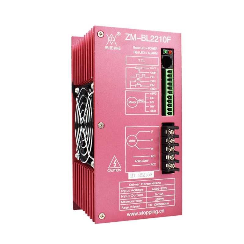
Driver wiring port description | ||
Function | Identification | Description |
Indicator light | POWER | green power indicator light, power on, indicating that the power supply is normal |
ALARM | red status indicator, slow flashing, waiting. fast flashing, running, and it changes with the motor speed, indicator always on for failure or offline | |
RS232 Communication port | TTL | can be connected to an external speed display board to display the speed; it can also be connected to a computer to set drive parameters |
Control signal terminal | 5V1 | Control signal power supply positive |
VSP | External speed control signal, adjust the motor speed through an external potentiometer | |
FG | Motor speed pulse output, can be converted into the actual speed of the motor by measuring the frequency of this signal | |
DIR | control the motor forward and reverse, connect to GND1, the motor will reverse, when not connected to GND1 , the motor will rotate forward, when switching between forward and reverse, in order to reduce the impact, first set EN to stop the motor | |
EN | Motor EN control, EN connects to GND1, the motor rotates, if EN is not connected to GND1, the motor does not rotate | |
ALM | Alarm output, when the circuit is in alarm state, output low level (OC gate output) | |
GND1 | Control signal power ground | |
Hall signal terminal | 5V2 | Motor Hall power supply positive |
HU | Hall sensor signal U phase input | |
HV | Hall sensor signal V phase input | |
HW | Hall sensor signal W phase input | |
GND2 | Motor Hall power ground | |
Motor and power terminal | U、V、W | Motor three-phase output signal, connected to motor winding |
AC1, AC2 | AC 80V~220V power supply input | |